A ground-mounted solar plant is one of the hardest environments on earth for satellite navigation. Between the rows the machine is surrounded by steel and glass, and the sky view is cut down to a narrow strip. Every GNSS-driven mower on the market behaves the same way there: the RTK status drops from Fixed to Float, and in the tightest corridors the fix is lost altogether. That is physics, not a defect. What separates one machine from another is what it does during those few seconds — and that is the entire subject of this guide.
Why RTK drops under PV arrays
Two physical effects are at work, and neither can be engineered away by any manufacturer.
- Signal occlusion. Panel surfaces and steel support structures block most of the sky view underneath the array. A GNSS receiver needs a wide spread of satellites overhead; under a panel it sees a slot, not a sky.
- Multipath reflection. Metal supports and glass surfaces bounce satellite signals. The receiver picks up the same signal twice — once direct, once delayed — and the computed position drifts.
The visible symptom is the RTK indicator flipping from Fix to Float. In Float the position error is measured in decimetres rather than centimetres. On a row with 2.5 m spacing, a decimetre of error is enough to matter.
- Occlusion — sky view reduced to the gap between rows
- Multipath — reflected signals corrupt the range measurement
- Symptom — RTK Fix becomes Float under the array, returns to Fix at the row end
- Scope — affects every GNSS-based mower, regardless of brand or price
The wrong question, and the right one
Buyers often ask “will it keep RTK Fix under the panels?” The honest answer from any manufacturer should be no — not at every point, not with current satellite geometry. The useful question is a different one: what does the machine do during the outage, and how quickly does it recover?
A mower that simply stops when it loses Fix is unusable in a solar plant. A mower that keeps driving on a stale position estimate will drift into a support post. The engineering that matters sits between those two failure modes.
The three-layer navigation stack on the WJ-T-1300M
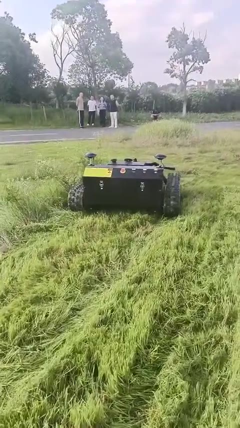
The WJ-T-1300M is a tracked brush cutter built for utility-scale vegetation work. Under the array it does not rely on satellites alone — it runs three positioning layers that hand off to each other.
Layer 1 — Multi-frequency, multi-constellation GNSS
The receiver tracks GPS, Galileo, BeiDou and GLONASS simultaneously. In North America, Galileo and GPS together provide a dense satellite set; compared with a single-frequency receiver this greatly improves satellite redundancy between support rows — more satellites means a better chance that enough of them are visible through the gap.
The antenna is mounted at elevated height specifically to prioritise sky-view access through the gaps between rows. Antenna placement is not a detail on a solar site; it is the difference between a usable fix and none at all.
Layer 2 — Inertial navigation (IMU dead reckoning)
When RTK drops, a 9-axis IMU combined with the odometer takes over and computes position continuously. Over short distances the drift stays restrained — the machine holds its line along the row instead of veering into a support or wandering off course.
The critical detail is what happens at the end of the row. The moment the machine reaches the open end of an array it re-acquires RTK Fix and resumes mowing from the break-point — no operator intervention, no missed strip.
Layer 3 — LiDAR SLAM and virtual fence
LiDAR identifies the support posts directly and uses them for relative positioning — an independent reference that does not depend on satellites at all. A PV-array map is pre-configured in the software, and the narrow under-panel corridors are defined as protected operating zones where travel speed is reduced.
In those corridors the machine prioritises LiDAR-based obstacle avoidance and relative positioning over satellite position. This is the layer that keeps it clear of the posts when the fix is at its weakest.
- Platform: rubber track
- Cutting deck: 4-blade
- Engine: Briggs & Stratton 810 cc, 27 hp — drives the cutting deck only
- Drive: battery pack drives the tracks — battery specification not published
- Fuel: 19.0 L tank, 6–7 h of operation
- Navigation: RTK-GNSS + 9-axis IMU + LiDAR SLAM
- Control: remote with live camera feed and manual override
Operating logic: what a run actually looks like
- Open row zones. Centimetre-level RTK Fix. The machine follows the planned path with no boundary wire.
- Under the panels. Fix is lost. IMU dead reckoning carries the position forward while LiDAR holds the line against the posts.
- Row end. RTK re-locks automatically and mowing resumes from the break-point.
- Repeat. The cycle runs across the whole block without an operator walking the rows.
Field validation: utility-scale PV in North America
The “RTK + IMU + LiDAR” combination is the mainstream technical approach for PV vegetation maintenance in North America, and it is already in regular service with multiple local O&M contractors.
In practice the machine holds RTK Fix across the open field areas, dead reckoning takes over during brief outages under the panels, and only very small zones around the support posts need manual touch-up. That last point is worth stating plainly rather than hiding: no GNSS-based mower covers 100% of the ground under an array without some hand work at the posts.
Sustaining RTK Fix at every single point underneath PV panels is physically unachievable for any GNSS-based mower. A vendor who promises it either has not measured it or is measuring something else. What can be promised is on the next section of this guide: stable travel along rows, no collision with supports, complete coverage, no course deviation.
Site deployment: four decisions that determine whether it works
- Base station. Mount it at a high-elevation, unobstructed position inside the plant. Installation underneath PV panels is strictly prohibited — a base station under an array broadcasts a corrupted correction. Where a local NTRIP or CORS service is available, connect to it and skip the maintenance of a self-built base entirely.
- Path planning. Put every turn and every row-switch at the open end zones of the arrays. Straight-line travel underneath the panels is what IMU and LiDAR are for; manoeuvring under panels is not.
- Antenna layout. Keep the GNSS antenna at elevated height and away from the metal chassis. Mounting it close to steel re-introduces the multipath problem that antenna height was meant to solve.
- No-go zones. Mark any location with persistently poor signal quality as a prohibited operating zone. A short manual strip is cheaper than a recovery operation.
Acceptance criteria: what to write into the contract
Because the limitation is physical and universal, acceptance criteria should be written around outcomes the machine can actually deliver:
- Stable travel along the rows
- No collision with support structures
- Complete mowing coverage of the specified work zone
- No course deviation
Put that list in the contract and leave out “RTK Fix at all times”. A specification that no product on the market can meet is not a quality standard — it is a dispute waiting to happen.
Quick answers
Why does the RTK status show Float under the panels?
Because the panels block the sky view and the steel reflects the signal. It is a physical limitation shared by every GNSS-based machine, not a fault of the unit.
Do we need to build our own base station?
Not necessarily. If a local NTRIP or CORS correction service covers the site, connect to it and skip the maintenance. If you do build one, mount it high and clear — never under the array.
How much manual work is left?
Very small zones immediately around the support posts. Everything else in the array is covered by the machine.
Can it run at night?
Yes — LiDAR and IMU do not depend on daylight. Ask us about the camera and lighting setup for your site.